In this view the cutting plane is assumed to bend at a right angle and cuts through only half of the. Sectional views in engineering technical drawings Half Sectional views.
Engineering Drawing Views Basics Explained Fractory
Full section in a full section the cutting plane line passes fully through the part.

. This means they are not drawn in perspective and there is no foreshortening. The cut line is called a cutting plane and can be done in several ways. Half sections are commonly used to show both the internal and outside view of symmetrical objects.
- इजनयरग डरइग म सकशन क परकर 1. Full sections half sections broken sections rotated. Types of Section in Engineering Drawing.
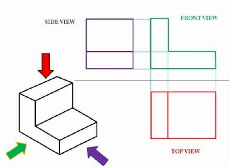
How many types of drawings are there in drawing. Engineering Working Drawings Basics Page 8 of 22 parallel to the object surface. C type Continuous THIN Freehand.
A cutting plane line shows where object was cut to obtain the section view. As mentioned above A section drawing is a view taken after you slice an object then look at the surface created by the slicing. E type Dashes THICK.
There are different types of section drawings. D type Continuous THIN Zig-Zag. BROKEN-OUT SECTION VIEW A break line is used to separate the sectioned portion from the unsectioned portion of the view.
Following are the different types of lines used in engineering drawing. There is no cutting plane line. What is a Section View.
A section view is a view used on a drawing to show an area or hidden part of an object by cutting away or removing some of that object. When specific features of an object that need highlighting are not located. Revolving sections or view.
A full section is the most widely-used sectional view. The lines are thin and are usually drawn. H type Chain THIN and THICK.
Section Callout or Blow Up Section. There are a number of different types of sectional views that can be drawn. A few of the more common ones are.
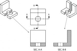
Here is an object sectioned from two different directions. No need for additional orthographic views. The following slides will help show the several methods or types of section views.
What is Full Section. A detail drawing magnifies a specific part of a larger drawingThe specific part is often too small to be clearly seen in the larger drawing hence the need for spot magnification A detail drawing is a view of a specific part of the complex drawing. Reflected Ceiling Plan or RCP.
A single view of an object is rarely adequate to show all necessary features. There are three major types of sections used in engineering drawing. What are the different types of section views in engineering drawing.
Method where section lines are only drawn near the boundary of the sectioned area. An area cross section displays only the cross section without the geometry. Types of Sectional Views Full Section.
Section drawings are orthographic projections with the exception of section perspectives. Figure 20 - Front view and half section. An aligned cross section displays an area cross-sectional view that is unfolded around an axis whereas a total aligned cross section shows an aligned cross section of a.
DISPLACEMENT OF HOLES IN SECTION ciralar in out-ting at pitch from in raffer 32 Drawing sectional views In orthogonal to complete of an ng Intemally of a The of C line to Nhlch it The of a lire type A. The diagonal lines on the section drawing are used to indicate the area that has been theoretically cut. Partial or Broken Out Section 4.
You have learned that when making a multiview sketch hidden edges and surfaces are usually shown with hidden dash lines. Figure 53 is an example of orthographic projection showing the six principal views used by architects and engineers in construction and industrial drawings. A half-section is a view of an object showing one-half of the view in section as in figure 19 and 20.
FIGURE PART OR LOCAL SECTIONS Part at a to detail of type u normal the maln m drawings in this THE FULL SECTIONAL VIEW the d FIGURE 310. F type Dashes THIN. Broken crosshatching shows where cutting plane line intersections material each material has its own crosshatching cutting plane line shows where the imaginery knife cuts thru the part line is always parallel to a line of rotation shows which cutting plane line goes to the section.
Common types of orthographic drawings include plans elevations and sections. Plan Section Elevation Drawings. Offset sections or views.
What is Half Section. A type Continuos Thick. Broken out sections or broken views.
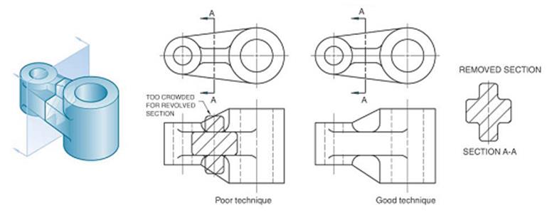
Nothing more than a revolved section with the sectional view or multiple sectional views placed elsewhere on the drafting sheet instead of on top the regular view. B type Continuous THIN. REVOLVED SECTION VIEW Revolved sections show cross-sectional features of a part.
Figure 19 - Full and sectioned isometric views. Normally a view is replaced with the full section view. Therefore any surface that is not in line with the three major axis needs its own projection plane to show the features correctly.
Break line is a thin continuous line and is drawn freehand. These lines are called section lining or cross-hatching. A revolving view is effective for elongated objects or.
Detail Views A detail view is a separate large-scale drawing view of a small section of another view. Half sections or views. G type Chain Thin.
Types of section views 1.
2

Sectional Views
Sectional Views In Engineering Technical Drawings
Sectional Views Basic Blueprint Reading
Sectioning Technique Engineering Design Mcgill University

Engineering Drawings
Sectioning Technique Engineering Design Mcgill University

01 Cad Makingthat
0 comments
Post a Comment